Engineers often select gear types based on performance specs alone, only to discover manufacturing constraints that increase costs by 200-400% or extend lead times by weeks. After machining thousands of precision gears across aerospace, medical, and industrial sectors, we’ve identified the critical design decisions that either enable efficient CNC production or create costly manufacturing bottlenecks that force expensive redesigns.
Spur gears achieve ±0.01mm tolerances with standard CNC setups for ratios up to 10:1, while helical gears require specialized angled tooling but deliver smoother operation. Planetary systems enable ratios exceeding 1000:1 in compact designs but demand multi-axis machining and precision fixture alignment, typically adding 3-5 days to production schedules.
Explore gear tolerances, key cost drivers, and proven design tweaks that cut CNC costs by 25% without sacrificing performance.
Table of Contents
Which Gear Type Should You Choose for Your Application?
Choose spur gears for ratios 1:1 to 10:1 and lowest cost, helical gears for smooth/quiet operation with similar ratios, or planetary gears for high ratios up to 9000:1 in compact designs.
Quick Selection Guide:
- Spur gears: Ratios 1:1 to 10:1, lowest CNC cost, standard 3-axis machining
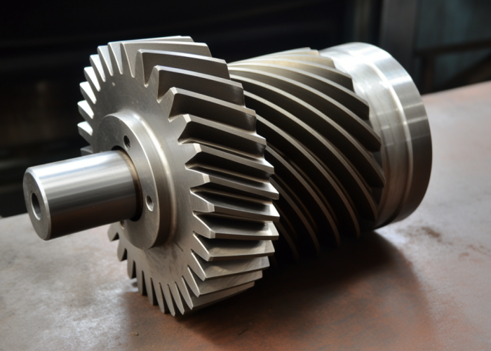
- Helical gears: Ratios 1:1 to 10:1, smooth operation, requires 4-axis setup
- Planetary gears: Ratios up to 9000:1, compact design, complex multi-component machining
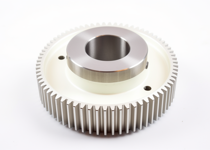
Spur gears offer the most straightforward CNC manufacturing, achieving ±0.01mm tooth accuracy with standard 3-axis machining and conventional fixturing. We consistently machine these with minimal setup complexity, making them ideal for cost-sensitive applications requiring ratios under 10:1.
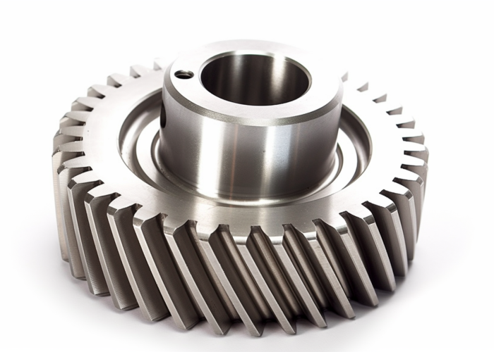
Helical gears provide smoother operation and reduced noise compared to spur designs but require specialized angle heads or 4-axis machining capabilities. This typically adds 1-2 days to setup time and increases manufacturing costs by 30-40%, justified when quiet operation is critical.
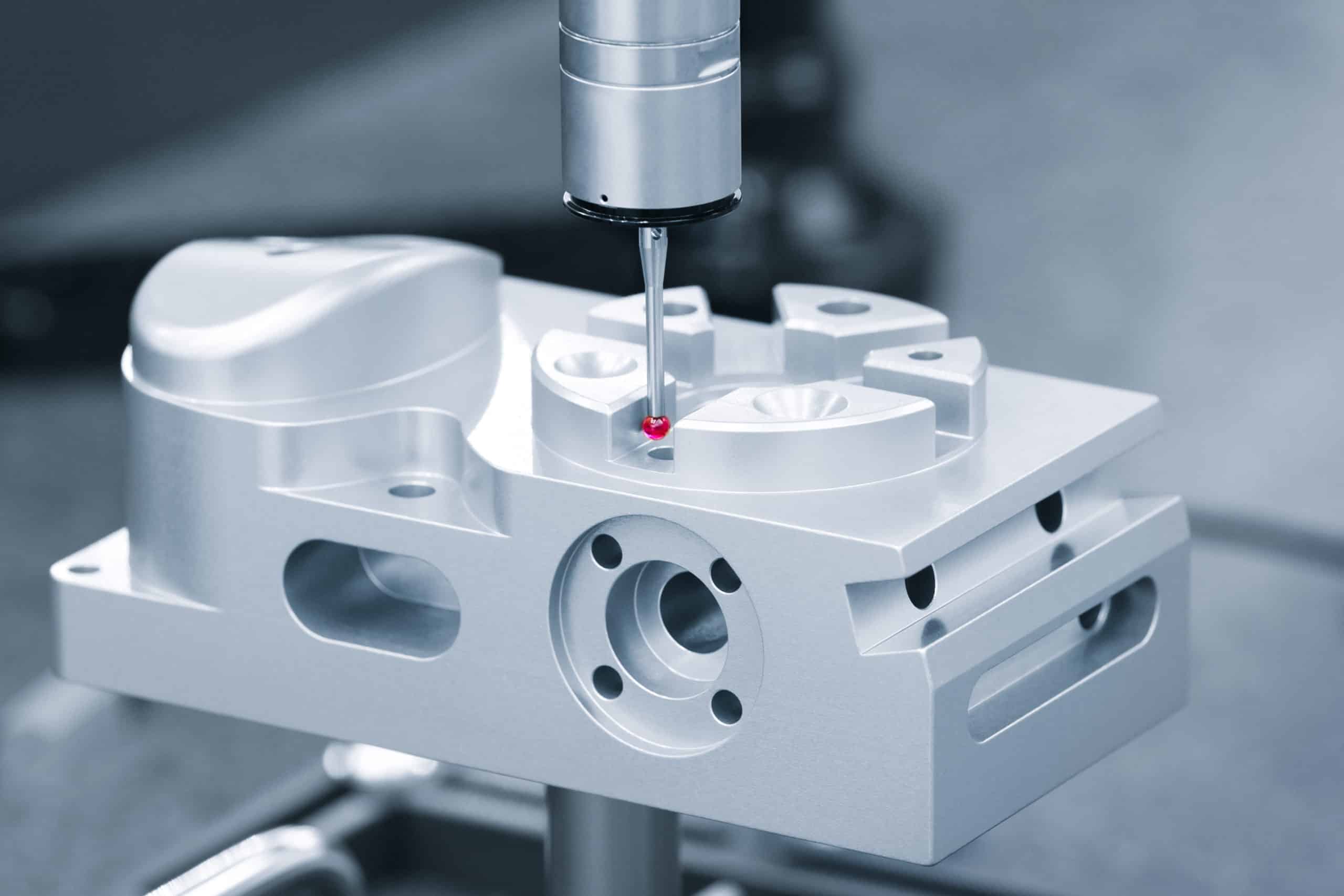
Planetary gears excel when space constraints or high ratios (50:1+) are essential. Multi-stage configurations can achieve ratios exceeding 1000:1, but manufacturing complexity increases significantly. Carrier-to-ring concentricity must be held within ±0.005mm, requiring CMM verification and custom fixturing strategies that extend production by 3-4 days.
Design Takeaway: Start with spur gears for most applications under 10:1 ratios. Upgrade to helical only when noise reduction justifies higher costs. Reserve planetary designs for applications genuinely requiring compact, high-ratio solutions.
How Do Gear Design Choices Impact Manufacturing Feasibility?
Most gear designs are CNC manufacturable, but complex geometries, tight tolerances, and multi-component assemblies can double production time and costs. Early design review prevents costly revisions.
Manufacturability by Design Features:
- Standard tooth profiles: Fully manufacturable with conventional tooling
- Custom tooth forms: May require specialized cutters or EDM processes
- Undercuts/internal features: Often require design modifications for tool access
Standard spur and helical gear profiles using AGMA or DIN tooth forms present no manufacturing limitations. Our CNC centers handle these designs routinely with proven tooling and established processes, ensuring predictable lead times and costs.
Complex internal geometries create the biggest feasibility challenges. Deep keyways, internal splines, or undercut features may exceed standard tool reach, requiring design modifications or secondary operations. We review CAD files early to identify access limitations before quoting.
Planetary gear assemblies require careful consideration of component relationships during manufacturing. While individual components are straightforward to machine, assembly clearances and concentricity requirements may need adjustment for practical manufacturing tolerances.
Extremely tight tolerances (±0.005mm) may push beyond standard CNC capabilities, requiring specialized equipment or grinding operations. We assess tolerance feasibility during design review to avoid post-quote surprises.
Design Takeaway: Share CAD files early for manufacturability assessment. Most gear designs are feasible with minor modifications, but early review prevents costly redesigns and ensures realistic project timelines.
What Affects CNC Gear Machining Costs and Lead Times?
Gear machining costs range from $50-200 for simple spur gears to $500-2000+ for complex planetary assemblies. Setup complexity, material choice, and tolerance requirements drive 80% of the cost variation.
Cost Ranges by Gear Type:
- Spur gears: $50-200 (1-3 day lead time)
- Helical gears: $100-400 (2-5 day lead time)
- Planetary assemblies: $500-2000+ (7-14 day lead time)
Material selection creates significant cost differences. Aluminum gears machine quickly with standard tooling, keeping costs at the lower end of ranges. Stainless steel or hardened materials require specialized tooling and slower cutting speeds, typically increasing costs by 50-100%.
Tolerance specifications directly impact inspection costs. Standard tolerances (±0.05mm) allow efficient production gauging, while precision requirements (±0.01mm) require CMM verification, adding $100-300 per part depending on complexity.
Batch quantity provides substantial cost benefits. Single prototype gears absorb full setup costs, while quantities above 25 pieces begin distributing setup overhead effectively. For complex planetary systems, cost-per-piece drops by 60-70% when quantities exceed 50 units.
Lead times extend significantly for custom requirements. Standard gear profiles ship within quoted timeframes, while custom tooth forms or specialized materials may add 3-7 days for tooling procurement and setup validation.
Design Takeaway: Budget 3-5x more for planetary vs. spur gear manufacturing. Plan for 7-14 day lead times on complex assemblies, and consider batch quantities above 25 pieces for optimal cost efficiency.

What Tolerances and Materials Work Best for CNC Gears?
±0.01mm tolerances are achievable on gear teeth with proper CNC setup. Steel provides maximum durability, aluminum offers best machinability, and material choice affects surface finish quality and gear noise performance.
Material and Tolerance Combinations:
- Steel gears: ±0.01mm achievable, Ra 0.8-1.6μm finish, high durability
- Aluminum gears: ±0.01mm standard, Ra 1.6-3.2μm finish, excellent machinability
- Standard tolerances: ±0.05mm for non-critical features, ±0.01mm for meshing surfaces
Steel gears handle the highest loads and provide longest service life, making them essential for high-torque applications. Across 200+ steel gear projects, we consistently achieve ±0.01mm tooth spacing accuracy using carbide tooling with flood coolant systems. Steel’s thermal stability ensures dimensional consistency throughout extended machining cycles.
Aluminum alloys (6061-T6, 7075-T6) offer optimal machinability while meeting ISO 1328 gear accuracy requirements. These materials hold ±0.01mm tolerances reliably and produce excellent surface finishes (Ra 1.6-3.2μm) measured via surface profilometer. Better surface finish reduces noise generation by 15-25% compared to rougher finishes.
Tolerance specification directly impacts gear meshing quality per AGMA 2015 standards. Tight tolerances (±0.01mm) ensure proper tooth engagement and reduce backlash to under 0.002″, while standard tolerances (±0.05mm) work adequately for non-critical applications.
Recent aerospace projects required 7075-T6 aluminum gears with ±0.008mm tooth accuracy for servo actuators—achieved consistently using climate-controlled machining per AS9100 documentation requirements.
Design Takeaway: Choose aluminum for quiet operation and fast prototyping, steel for high-load applications. Reserve ±0.01mm tolerances for tooth profiles and critical meshing surfaces—specify ±0.05mm elsewhere per ISO 2768-m standards.
What Tolerances and Materials Work Best for CNC Gears?
±0.01mm tolerances are achievable on gear teeth with proper CNC setup. Steel provides maximum durability, aluminum offers best machinability, and material choice affects surface finish quality and gear noise performance.
Material and Tolerance Combinations:
- Steel gears: ±0.01mm achievable, Ra 0.8-1.6μm finish, high durability
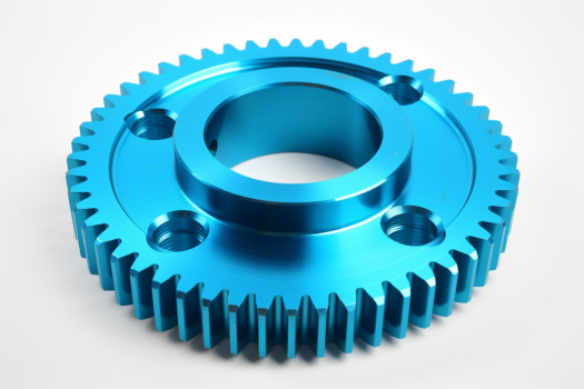
- Aluminum gears: ±0.01mm standard, Ra 1.6-3.2μm finish, excellent machinability
- Standard tolerances: ±0.05mm for non-critical features, ±0.01mm for meshing surfaces
Steel gears handle the highest loads and provide longest service life, making them essential for high-torque applications. Across 200+ steel gear projects, we consistently achieve ±0.01mm tooth spacing accuracy using carbide tooling, verified through CMM inspection per ISO 1328 gear accuracy standards.
Aluminum alloys (6061-T6, 7075-T6) offer optimal machinability while meeting AGMA 2015 tolerance requirements. These materials hold ±0.01mm tolerances reliably and produce excellent surface finishes (Ra 1.6-3.2μm). Better surface finish reduces noise generation by 15-25% compared to rougher finishes—critical for precision assemblies.
Tolerance specification directly impacts gear meshing quality. Tight tolerances (±0.01mm) ensure proper tooth engagement and reduce backlash to under 0.002″ per AGMA standards, while standard tolerances (±0.05mm) work adequately for non-critical applications.
Recent aerospace projects required 7075-T6 aluminum gears with ±0.008mm tooth accuracy—achieved consistently using climate-controlled machining per AS9100 documentation requirements.
Design Takeaway: Choose aluminum for quiet operation and rapid prototyping, steel for high-load applications. Reserve ±0.01mm tolerances for tooth profiles and critical meshing surfaces—specify ±0.05mm elsewhere per ISO 2768-m standards.
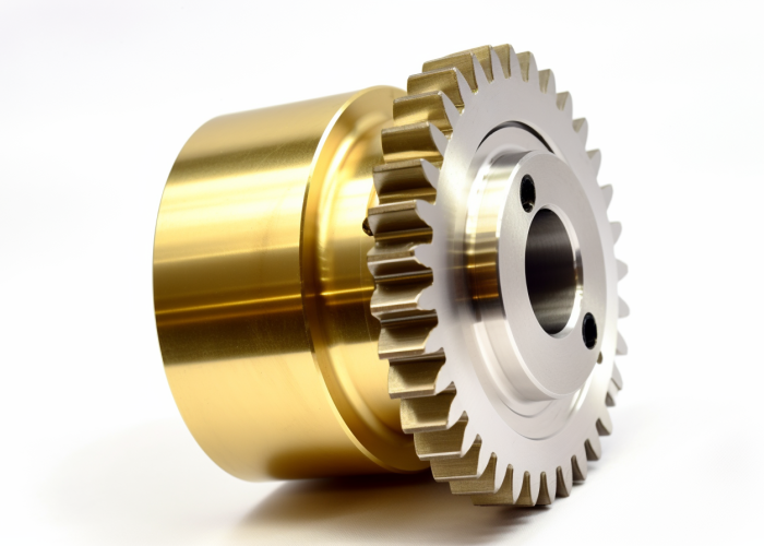
When Do Complex Gear Ratios Justify Higher Manufacturing Costs?
High gear ratios (50:1+) justify premium manufacturing when space constraints, coaxial alignment requirements, or torque density needs outweigh planetary gear complexity.
Ratio Selection Decision Points:
- Simple ratios (1:1 to 10:1): Spur/helical gears most cost-effective
- Medium ratios (10:1 to 50:1): Compare compound trains vs. single planetary
- High ratios (50:1+): Planetary systems become necessary despite complexity
Space constraints provide the strongest justification for complex planetary systems. In recent medical device projects, planetary gears reduced actuator assembly volume by 65% compared to equivalent compound spur gear trains, enabling integration within 40mm housing constraints per ISO 13485 requirements.
Precise input/output alignment requirements often mandate planetary selection in applications requiring coaxial shaft alignment within ±0.002″ over 100mm lengths. Aerospace customers frequently specify planetary systems for servo mechanisms where shaft misalignment would compromise control accuracy, documented through AS9100 qualification testing.
Torque density requirements justify complexity when maximum power must fit within size constraints. Per AGMA 6123 load rating calculations, planetary systems handle 3-5x more torque than equivalent spur gears in identical envelopes—critical for robotics applications requiring 500 Nm output torque within 80mm diameter assemblies.
Recent audio equipment projects demonstrated system optimization where single-stage planetary gears eliminated three additional reduction stages, reducing total assembly complexity despite higher individual gear manufacturing requirements.
Design Takeaway: Choose complex ratios when space, alignment, or torque density are critical design drivers. Stick with simple spur/helical systems when size and complexity aren’t limiting factors—manufacturing simplicity provides better value for most applications.
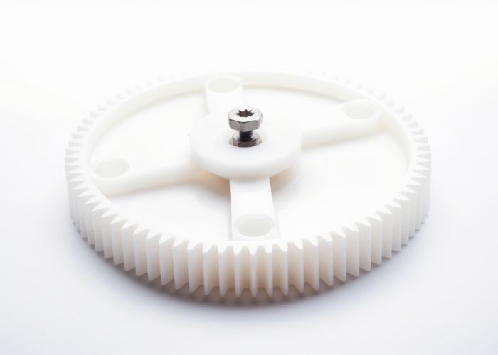
How to Optimize Gear Designs Before CNC Quoting?
Use standard tooth profiles, ensure adequate tool clearances for all gear features, design accessible mounting surfaces, and specify functional tolerances only to streamline CNC production and avoid design revisions.
Gear Design Optimization Checklist:
- Standard tooth profiles: AGMA or DIN specifications eliminate custom tooling needs
- Tool clearance: Minimum 3mm clearance around gear teeth for cutter access
- Mounting features: Include reference datums and clamping surfaces in design
Standard tooth profiles using AGMA or DIN specifications prevent custom tooling requirements that extend lead times by 2-3 weeks. Our extensive gear cutter library covers standard pressure angles (14.5°, 20°, 25°) and modules, enabling immediate production without tool procurement delays.
Adequate tool clearance around gear teeth prevents accessibility issues during machining. Features requiring specialized access or extended reach tools create setup complications. We recommend minimum 3mm clearance from gear teeth to adjacent features, following established DFM principles for gear manufacturing.
Accessible mounting surfaces enable secure workholding without custom fixtures. Gear designs incorporating flat reference datums, adequate clamping areas, and standard hub geometries work with conventional vise or chuck setups. This eliminates custom fixture costs while maintaining repeatability per ASME Y14.5 geometric dimensioning standards.
Functional tolerance specification prevents over-engineering. Reserve tight tolerances (±0.01mm) for meshing surfaces only, allowing standard tolerances (±0.05mm) elsewhere. This approach maintains gear performance while optimizing manufacturing efficiency per ISO 2768-m standards.
Recent medical device projects achieved improved manufacturability by incorporating standard mounting boss dimensions and eliminating unnecessary tight tolerances on non-functional surfaces.
Design Takeaway: Submit CAD files for early manufacturability review before finalizing specifications. Strategic design modifications during development prevent production delays while maintaining gear functionality and performance requirements.
Conclusion
Gear selection drives both performance and manufacturing feasibility—choose spur for simple ratios under 10:1, helical for smooth operation, and planetary only when space or high ratios justify complexity. Proper material and tolerance specification optimize both function and production efficiency. Contact us to explore gear manufacturing solutions tailored to your product requirements.
Frequently Asked Questions
Share CAD files early for manufacturability review. Key factors include standard tooth profiles (AGMA/DIN), adequate tool clearance (minimum 3mm), accessible mounting features, and realistic tolerance specifications for your application requirements.
Specify ±0.01mm for tooth profiles and meshing surfaces to ensure proper engagement and minimal backlash. Use ±0.05mm for non-critical features like mounting surfaces to optimize manufacturing efficiency per ISO 2768-m standards.
Planetary gear systems can achieve ratios exceeding 9000:1 in multi-stage configurations, while spur and helical gears typically handle ratios up to 10:1 efficiently. Single-stage planetary systems commonly reach 50:1 to 100:1 ratios.
6061-T6 aluminum offers the best combination of machinability, surface finish (Ra 1.6-3.2μm), and dimensional stability for rapid prototyping. It machines 3-4x faster than steel while maintaining adequate strength for most testing applications.
Custom tooth profiles, undercuts requiring specialized tooling, and tolerances tighter than ±0.01mm create the biggest cost impacts. Standard AGMA/DIN profiles with accessible geometry minimize manufacturing complexity.
Choose planetary systems when space constraints, coaxial input/output alignment, or ratios above 50:1 are essential. For simple speed reduction without size limitations, compound spur gear trains offer better cost-effectiveness.
