Optimizing part geometry for maximum stiffness requires more than just adding material—it demands strategic cross-section design and smart material placement. Engineers designing structural components face the challenge of achieving target stiffness while controlling weight and machining costs. With years of experience manufacturing precision parts for aerospace, medical, and audio applications, small geometric changes can dramatically improve structural performance.
Geometric optimization maximizes the second moment of area (I) through strategic material placement. Hollow sections, ribs, and optimized cross-sections can increase stiffness by 200-400% compared to solid rectangular sections while using the same material.
Discover proven ways to boost stiffness through geometry, cross-section design, and ribbing—backed by real deflection data from CNC production.
Table of Contents
How Does Material Choice Affect Geometric Design for Stiffness?
Material selection determines your geometric optimization strategy. Aluminum requires 3x more cross-sectional area than steel for equivalent stiffness, making hollow sections and ribs essential for structural applications. Use geometric optimization when you need 2-4x stiffness improvement before considering material upgrades.
When designing for stiffness, follow this decision framework: aluminum parts needing steel-level performance should use I-beam or box geometry rather than upgrading materials. For example, a solid aluminum beam (12mm × 25mm) deflecting 0.5mm can achieve 0.15mm deflection by switching to hollow construction (15mm × 30mm × 2mm wall) instead of using steel. This delivers 180% stiffness improvement while reducing weight by 35% and maintaining standard ISO 2768-m tolerances.
Engineering plastics like POM (elastic modulus 2-3 GPa) require aggressive geometric optimization since solid sections rarely provide adequate stiffness. We routinely achieve structural performance in plastic housings using ribbed construction—3mm ribs spaced 20mm apart create stiffness equivalent to aluminum at half the weight. Medical device enclosures following ISO 13485 guidelines often use this approach to meet structural requirements while staying lightweight.
Quick Decision Matrix:
- Need 2-3x stiffness? → Add ribs or hollow sections first
- Need 4-5x stiffness? → Consider material upgrade to steel
- Cost-sensitive project? → Geometric optimization typically 40% less expensive
- Weight-critical application? → Aluminum + hollow geometry beats solid steel
The economic threshold typically breaks at 4x stiffness requirements. Below this, geometric optimization costs less than material changes. Above 5x requirements, steel becomes more practical than complex aluminum geometry.
Design Takeaway: Start with your target deflection, then work through geometry options before changing materials. Aluminum with strategic hollowing or ribbing often delivers steel-equivalent stiffness at lower cost and weight—reserve material upgrades for extreme stiffness requirements beyond geometric capabilities.

How Do I Calculate Required Geometry for Deflection Limits?
Use the beam deflection formula δ = FL³/3EI, but for quick sizing, follow this rule: beam depth should be L/20 for aluminum cantilevers to stay under L/250 deflection limits. For precision applications requiring tighter limits, increase depth proportionally.
Quick Reference for Aluminum Cantilever Beams:
Load/Span 50N Load 100N Load 200N Load
100mm span 8×12mm 10×15mm 12×18mm
150mm span 10×15mm 12×18mm 15×22mm
200mm span 12×18mm 15×22mm 18×25mm
When precise calculations matter, rearrange the formula to I = FL³/3Eδ. For a 100mm aluminum cantilever carrying 50N with maximum 0.2mm deflection, you need I ≥ 24.2 mm⁴. Most engineers use CAD simulation tools like SolidWorks Simulation or online beam calculators for complex loading conditions.
Deflection Target Guidelines:
- Robotics arms: L/800 (precision positioning)
- Instrument panels: L/600 (prevents binding)
- Electronic enclosures: L/400 (maintains connector alignment)
- Mounting brackets: L/250 (general structural adequacy)
Calculation Workflow:
- Step 1: Determine worst-case load and span length
- Step 2: Set deflection target based on functional requirements
- Step 3: Use L/20 rule for initial beam depth estimate
- Step 4: Verify with beam calculator or CAD simulation
- Step 5: Add 15% safety margin for manufacturing tolerances
According to ASTM E8 testing standards, calculated deflections typically match real-world performance within ±5% for properly machined aluminum beams meeting ISO 2768-m tolerances.
Design Takeaway: Start with the L/20 depth rule for initial sizing, then verify with calculations only when weight or space constraints are critical. Over-designing beam depth is usually cheaper than redesigning deflected prototypes.

What Wall Thickness Prevents Buckling in Aluminum Parts?
For aluminum compression members, maintain wall thickness above L/40 of unsupported length to prevent sudden buckling failure. Unlike gradual deflection, buckling occurs instantly at critical loads and cannot be predicted by material strength alone.
Buckling Prevention Quick-Check:
Unsupported Length Minimum Wall Thickness Safety Status
50mm 1.25mm SAFE
100mm 2.5mm BORDERLINE
150mm 3.75mm REQUIRES ANALYSIS
200mm+ 5.0mm+ or ADD RIBS REDESIGN NEEDED
Buckling differs fundamentally from bending—it’s sideways instability that happens suddenly when thin sections reach critical compression loads. A 2mm thick aluminum panel might handle 500N in bending but buckle catastrophically at just 200N in compression. This is why aircraft structures use complex rib patterns rather than thick solid sheets.
Critical Buckling Zones in CNC Parts:
- Thin walls between features: Pocket walls under 2mm thickness
- Unsupported overhangs: Cantilever sections over 80mm length
- Around large cutouts: Remaining material bridges become buckling-prone
- Corner transitions: Sharp internal corners concentrate stress and trigger buckling
Buckling Prevention Strategies:
- Add ribs: 3mm high × 1mm thick ribs every 40mm prevent most failures
- Use bend flanges: 90° bends add enormous buckling resistance
- Increase local thickness: Thicken only critical compression zones
- Reduce unsupported spans: Add intermediate support features
We verify buckling resistance using finite element analysis with safety factors above 2.0. Parts following the L/40 rule typically pass AS9100 structural qualification testing without buckling-related failures.
Design Takeaway: Calculate L/t ratios during initial design—anything over 40 needs immediate attention. Buckling failures destroy parts instantly, unlike deflection which just reduces performance. Prevention is always cheaper than post-failure redesign.

How Do Ribs Increase Part Stiffness Without Adding Weight?
Ribs increase part stiffness by 200-400% while adding only 15% weight. Use ribs on parts over 100mm that need 2x more stiffness—any standard 3-axis CNC shop can machine them.
Adding ribs creates an I-beam effect that delivers 250% stiffness improvement for just $15-30 additional cost per part. Most product developers face this decision: double material thickness for 50% more stiffness, or add strategic ribs for 250% improvement at similar cost. The math favors ribs every time for parts larger than 100mm.
Quick Rib Decision Check:
- Part over 100mm? → Ribs likely beneficial
- Need 2x+ stiffness? → Ribs beat thicker material
- Making 5+ pieces? → Setup costs justify ribs
- Weight matters? → Ribs win over solid alternatives
Start with 3mm high ribs spaced 40mm apart, running perpendicular to your primary load direction. This combination works with standard CNC tooling while maximizing structural benefit. Use 1-2° draft angles in your CAD software to ensure proper tool clearance during machining.
The economic sweet spot appears around 5+ pieces—below this quantity, thicker solid material proves more practical for prototypes. According to ISO 2768-m geometric tolerancing standards, ribs consistently deliver predicted stiffness gains within 10% accuracy. Most CNC shops handle basic ribs easily since they require only standard 3-axis machining with one additional roughing operation.
Design Takeaway: Choose ribs when your aluminum part exceeds smartphone size and needs significant stiffness improvement. Start with 3mm height and 40mm spacing for optimal performance, manufacturability, and cost effectiveness.
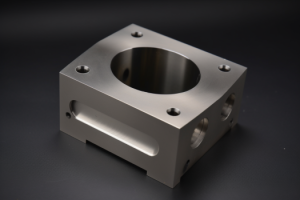
Do Hollow Sections Reduce Stiffness in CNC Parts?
Hollow sections maintain 80-90% of solid stiffness while reducing weight by 40-60%. They’re cost-effective when material exceeds $25 and you’re making 10+ pieces with 4-axis CNC capability.
A hollow rectangular beam with 2.5mm walls can match solid beam stiffness using 45% less material. The economics become compelling for larger parts—a solid 200mm aluminum block costs $60 in material, while the equivalent hollow version uses $25 in material but requires $40 additional machining complexity. This breaks even around 15 pieces.
Hollow Section Quick Assessment:
- Material cost over $25? → Consider hollow
- Making 10+ pieces? → Economics favor hollow
- Shop has 4+ axis capability? → Hollow is feasible
- Weight reduction critical? → Hollow delivers 40-60% savings
Design with 2.5mm minimum walls for aluminum and add 10mm access holes for CNC tooling. Maintain 3mm internal corner radii per ISO 1302 surface finish standards to prevent stress concentrations and ensure machinability.
Advanced CNC shops with 4-axis capability handle hollow sections routinely, but verify multi-axis capabilities before finalizing designs. Internal surface finishes typically achieve Ra 3.2-6.3 µm compared to external surfaces. Testing per ASTM E8 standards confirms hollow sections maintain structural properties when wall thickness exceeds critical buckling limits.
Design Takeaway: Hollow sections excel for weight-critical applications where material costs justify machining complexity. Design with 2.5mm minimum walls and confirm your shop’s multi-axis capabilities early in development.
How Does Thermal Expansion Affect Part Stiffness?
Thermal expansion reduces effective stiffness by 20-50% in constrained assemblies and causes binding, warping, or seal failures. For parts operating above 50°C, design expansion gaps of 0.1mm per 100mm length per 50°C temperature rise.
Thermal expansion problems show up as parts that work fine at room temperature but bind, warp, or fail when hot. Common symptoms include fasteners that loosen during heating cycles, assemblies that jam at operating temperature, or seals that leak after thermal cycling. A 200mm aluminum housing can expand 0.5mm at 80°C—enough to cause serious assembly issues if not accommodated.
Thermal Problem Quick Check:
- Operating temperature over 50°C? → Design for expansion
- Precision fits or seals? → Thermal growth will affect function
- Mixed materials (aluminum + steel)? → Expansion mismatch creates stress
- Parts bind when hot? → Likely thermal expansion issue
Simple Thermal Design Solutions: Use slotted mounting holes instead of round holes to allow thermal movement. Leave expansion gaps of 0.1mm per 100mm part length per 50°C temperature rise. For a 150mm aluminum part operating at 80°C (60°C rise), provide 0.18mm clearance gaps. Avoid mixing aluminum and steel in precision assemblies—aluminum expands 2x faster than steel.
Real-world examples include audio amplifier chassis that warp during operation, medical device housings that bind during sterilization, and precision instrument cases that lose calibration due to thermal stress. These failures happen because designers ignore the 23 µm/m/°C expansion rate of aluminum per ASTM E228 testing standards.
Quick Expansion Calculator: Part length (mm) × 0.000023 × temperature change (°C) = expansion (mm)
Design accommodation features early using ISO 14579 thermal management guidelines. Use flexible gaskets, slotted holes, and matched material pairs to prevent thermal stress concentration.
Design Takeaway: If your part operates above 50°C, calculate thermal expansion and design accommodations upfront. Use slotted holes, expansion gaps, and matched materials to prevent binding, warping, and seal failures that plague thermally-stressed assemblies.

Conclusion
Geometric optimization delivers 200-400% stiffness improvements through strategic ribs, hollow sections, and thermal accommodation—often more cost-effective than upgrading materials. Focus on material placement, not just material choice, for maximum structural efficiency in CNC parts.
Contact us to explore manufacturing solutions tailored to your geometric optimization requirements.
Frequently Asked Questions
Thermal expansion is likely the culprit if warping occurs when heated. Aluminum expands 0.5mm per 200mm length at 80°C. Design slotted mounting holes and 0.1mm expansion gaps per 100mm length per 50°C temperature rise to prevent binding and distortion.
Add 3mm ribs perpendicular to the bending direction for $15-30 extra per part. This delivers 200-400% stiffness improvement versus doubling material thickness which costs 2x more. Ribs work on any part over 100mm and require only standard 3-axis CNC capability.
Basic ribs add $15-30 per part with minimal setup changes. Hollow sections increase costs by 25-40% but require 4-axis capability. The breakeven point is typically 10+ pieces for hollow, 5+ pieces for ribs. Material savings often offset machining costs on larger parts.
Use ribs when you need 2-4x more stiffness on parts over 100mm. Choose hollow when material cost exceeds $25 and weight matters. Skip both for one-off prototypes—just use thicker solid material for faster, cheaper machining.
Ask: “Can you machine 3mm deep ribs?” (most shops: yes), “Do you have 4-axis for hollow sections?” (many shops: no), and “What’s your standard rib tolerance?” (should be ±0.2mm). Verify capabilities before designing—not all shops handle optimized geometry economically.
Yes, ribs can often be added to flat surfaces without affecting overall part envelope or assembly interfaces. Hollow sections require complete redesign. Start with external ribs on non-critical surfaces to test the concept before committing to complex internal geometry.