Steel selection affects both part performance and machining cost. With years of experience machining components for aerospace and medical applications, small material choices can dramatically impact your project’s success and budget.
Start with 1018 carbon steel for general brackets and housings, upgrade to 4140 for high-strength applications, or choose 304/316 stainless when corrosion resistance is required. Material selection depends on load requirements, operating environment, and machining budget constraints.
Learn how to choose the right steel grade, compare real-world trade-offs, and find the best options for CNC work—plus cost and machinability tips.
Table of Contents
How do I choose the right steel grade for my specific part?
Start with part type and load: Brackets/housings under 500 lbs = 1018 carbon steel. Shafts/pins or 500-1000 lbs = 1045 carbon steel. High-stress parts over 1000 lbs = 4140 steel. Any outdoor/wet exposure = 304 stainless steel. These four grades handle 90% of CNC applications.
Quick Decision Table:
Part Type Load Range Environment Steel Grade What Happens If Wrong
Brackets, Housings Under 500 lbs Indoor 1018 Bends if overloaded
Shafts, Pins 500–1000 lbs Indoor 1045 Premature wear
Critical parts Over 1000 lbs Indoor 4140 Overpaying if 1045 works
Any part Any load Outdoor/Wet 304 SS Rust within months
Over the past decade machining precision components, we’ve learned that most engineers jump to 4140 when 1045 would work fine, adding unnecessary cost and machining complexity. We recently helped a client switch from 4140 to 1045 for motor brackets, saving 40% on material costs with zero performance loss.
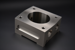
1018 for Standard Brackets: Handles typical equipment mounts and housings. We hold ±0.01″ tolerances easily on most features. A recent audio equipment faceplate project used 1018 throughout – zero failures after 18 months in the field.
1045 for Moving Parts: About 35% stronger than 1018 and machines well. Use for anything that rotates, slides, or sees repeated loading. We machine conveyor rollers and pivot shafts from 1045 with excellent results.
4140 for Serious Loads: Heat-treats to very high strength when needed. One aerospace client required this for landing gear brackets – the extra strength was functionally necessary, not just conservative engineering.
304 Stainless for Wet/Outdoor: Resists atmospheric corrosion per ASTM A240. We’ve machined food processing housings that still look new after 3 years of daily washdowns.
Design Takeaway: When in doubt, start one grade lower than your gut says. Test your prototype under real conditions. Upgrade only if you see actual bending, wear, or corrosion. This prevents over-engineering while catching real performance gaps early.
What's the difference between carbon steel and stainless steel?
Carbon steel costs less and machines faster but needs coating for protection. Stainless steel costs 3x more and machines slower but never rusts. Choose based on where your part lives and how it needs to look after 3 years.
Quick Environment Decision: Indoor + dry = carbon steel with coating. Anything seeing humidity, condensation, or outdoor exposure = stainless steel.
After machining both materials for years, environment beats strength specs every time. Carbon steel machines significantly faster than stainless, affecting your cycle times and costs. But we’ve re-machined failed parts where clients chose carbon steel in wet environments.
A warehouse client’s brackets started showing rust within 12 months near loading docks where trucks brought moisture and road salt. Switching to 304 stainless eliminated the problem entirely.
Material Performance: 304 stainless steel actually exceeds 1018 carbon steel in tensile strength while adding corrosion protection. You’re not sacrificing performance, just paying more upfront. Total part cost typically increases 150-200% due to slower machining.
For indoor equipment staying dry, coated carbon steel lasts 10+ years without issues. We’ve machined server components and HVAC brackets that still look new after 5 years in climate-controlled environments.
Design Takeaway: When environment exposure is uncertain, test both materials in your actual conditions for 3-6 months. Start with carbon steel for prototypes, switch to stainless for production if needed.

Is 1018 steel strong enough for my bracket design?
1018 steel handles most brackets under reasonable loads, but your safety factors and design geometry matter more than material strength numbers. Use the 3x load rule plus hand-flex testing to avoid field failures.
Load Reality Check: That 30-lb motor becomes a 90-lb design load when factoring shipping shock, vibration, and safety margins. We apply 3x safety factors to stated loads – prevents warranty issues on dynamic equipment.
Simple Testing Method: Mount your prototype and load it at 3x expected loads. No visible deflection = approved. Noticeable bending = upgrade to 1045 steel or add reinforcement. This catches 95% of strength issues before production.
Thickness Guidelines: Brackets under 0.25″ thick usually flex excessively – we recommend 1045 minimum for thin sections. Over 0.5″ thick, 1018 handles most applications. Sweet spot is 0.375″ thick 1018 for general equipment mounting.
Geometry Beats Materials: Adding flanges or corner gussets often triples strength without changing steel grades. Recent client’s brackets went from failing at 200 lbs to handling 600 lbs using identical 1018 with formed edges.
When 1018 Fails: Dynamic applications with repeated loading cycles where fatigue develops. Static mounts work fine; vibrating equipment usually needs 1045 minimum.
Design Takeaway: Start with 1018, test at 3x loads. Add geometry features before upgrading materials – most bracket issues are design problems, not material problems.
Should I spec stainless steel or will coated carbon steel work?
Use coated carbon steel for indoor, dry environments where appearance isn’t critical. Choose stainless steel when your part sees moisture, needs professional appearance long-term, or maintenance access is difficult. Factor coating costs and replacement cycles into your total budget.
We’ve tracked coating performance across hundreds of parts to give you realistic expectations. Powder coating adds $15-25 per part but lasts 10+ years indoors. Zinc plating costs $5-10 per part but starts showing wear in humid conditions after 2-3 years.
Coating Performance & Cost Reality:
Coating Type Cost Per Part Indoor Life Outdoor Life Best For
Powder Coat $15–25 10+ years 5–7 years Appearance parts
Zinc Plating $5–10 8+ years 2–3 years Basic protection
No Coating $0 6–18 months 3–6 months Hidden parts only
304 Stainless Material cost 3x Indefinite Indefinite Long-term solution
What Coating Failure Actually Looks Like: Year 1-2: Perfect appearance. Year 3-4: Minor scuffs and wear at contact points. Year 5-6: Noticeable fading or chalking outdoors. Year 7+: Touch-up needed for professional appearance.
A food processing client learned this the hard way – daily washdowns destroyed powder coating within 8 months, forcing expensive recoating cycles. Switching to 304 stainless eliminated maintenance costs entirely.
Retrofit Reality Check: You can strip and recoat carbon steel parts, but it typically costs 80% of making new stainless parts. We usually recommend starting over with stainless steel rather than trying to salvage failed coatings.
Design Takeaway: Calculate total cost over your product’s expected life. If maintenance access is difficult or recoating costs approach stainless pricing, choose stainless steel initially.
Which steel machines faster without sacrificing strength?
1045 carbon steel offers the best speed-to-strength balance for most applications – machines cleanly while providing 35% more strength than 1018. Avoid 4140 for production runs over 50 pieces due to extended cycle times.
After machining thousands of parts, we’ve learned that material choice can double your machining costs on production runs. 1045 saves 2-3 days on 100-piece orders versus 4140, while 12L14 machines fastest but lack structural strength.
Machining Time & Cost Impact:
oad Level Rotation Speed Environment Steel Choice Heat Treatment
Light Any Indoor 1045 Optional
Medium High RPM Indoor 1045 Required
Heavy Any Indoor 4140 Required
Any Any Outdoor/Wet 17-4 PH SS Age hardened
Real Production Impact: A recent 100-piece bracket run took 5 days in 1045 versus 8 days in 4140 – that’s $800 extra labor cost just from material choice. The 4140 also required premium tooling due to work hardening, adding another $200 in tool replacement.
Volume Decision Rules: Under 10 pieces: Material choice barely affects timeline or cost – choose based on strength requirements. 10-50 pieces: 1045 provides a good balance of speed and strength. Over 50 pieces: Machining time becomes significant cost factor – only use 4140 if strength calculations prove it’s necessary.
Tool Life Reality: 4140 reduces carbide tool life by 50-70% compared to 1045, adding hidden costs beyond cycle time. We factor $3-5 per part in additional tooling costs when quoting harder steel grades for production runs.
Design Takeaway: Start with 1045 for most applications requiring both reasonable machining speeds and adequate strength. Only specify 4140 when your load calculations prove lower grades inadequate – the machining cost penalty is significant.

How do I know if my part needs heat treatment?
Heat treat steel when your part has wear surfaces or repeated loading. Skip it for static brackets and housings. Heat treatment affects part dimensions and design constraints – plan these into your geometry early.
We see engineers specify heat treatment without considering the design implications. Heat treatment grows parts by 0.002-0.005″ and can warp asymmetric geometry, breaking tight assemblies or causing interference fits.
Design Your Tolerance Budget: If your assembly tolerance is ±0.010″ or looser, heat treatment growth won’t break your design. For tighter fits, either design looser tolerances or plan for post-heat-treatment machining (which adds cost and lead time).
Geometry Tips to Prevent Warping: Design symmetric parts – avoid heavy sections on one side that cause uneven stress relief. A bracket with mounting tabs on one side will warp during heat treatment. Balance your geometry or accept the warping.
Avoid Sharp Internal Corners: Heat treatment cracks sharp corners due to stress concentration. Design minimum 0.030″ radii on all internal features, especially where thin and thick sections meet. We’ve seen parts crack at sharp transitions during heat treatment.
Selective Hardening Strategy: You can specify which surfaces need hardening rather than treating entire parts. Mark wear surfaces on your drawings – this reduces distortion while hardening only functional areas. Saves cost and prevents assembly problems.
Common Heat Treatment Mistakes: Don’t heat treat threaded features – threads distort and may not assemble. Don’t heat treat thin walls under 0.125″ – they warp excessively. Don’t heat treat complex assemblies – do it at component level.
Design Takeaway: Plan heat treatment into your design early. Use symmetric geometry, generous radii, and realistic tolerance budgets. Specify selective hardening for wear surfaces only – whole-part treatment often causes more problems than it solves.
Do I need 316 stainless for my food processing equipment part?
Use 304 stainless for most food applications – it machines cleaner and costs less. Upgrade to 316 only for chloride exposure. Both grades affect your design constraints similarly, so choose based on environment, not manufacturability.
Food processing parts need special design considerations for cleanability and strength. Surface finish requirements add lead time – smooth cleanable surfaces take longer to machine than standard finishes.
Design for Cleanability: Avoid sharp internal corners where bacteria can hide – FDA guidelines recommend minimum 0.125″ radii for food contact surfaces. Eliminate horizontal surfaces that collect debris. Design self-draining geometry with sloped surfaces.
Avoid Deep Narrow Features: Deep pockets with narrow openings are difficult to machine and clean. Stainless steel chips are stringy and jam in tight spaces. Design wider access for both manufacturing and cleaning. If deep features are required, add multiple access points.
Weld Design Considerations: Both 304 and 316 weld similarly, but welded joints need smooth, crevice-free profiles for food safety. Avoid lap joints that create bacteria traps. Use butt joints with full penetration welds that can be ground smooth.
Structural Design Tips: Stainless steel is stronger than you think – 304 stainless exceeds mild steel strength. You can often use thinner sections than carbon steel designs, but avoid very thin walls under 0.060″ that are difficult to weld cleanly.
Surface Finish Planning: Food contact surfaces need Ra 32 μin or smoother – plan this into your schedule and budget. Non-contact surfaces can use standard finishes to save cost. Mark surface finish requirements clearly on your drawings.
Common Food Equipment Design Mistakes: Don’t design horizontal ledges that collect debris. Don’t use fasteners where welds would work better. Don’t specify unnecessary tight tolerances that add cost without improving cleanability.
Design Takeaway: Design for cleanability first – smooth surfaces, generous radii, self-draining geometry. Choose material grade based on your cleaning chemicals, not strength requirements. Plan extra time for smooth surface finishes on food contact areas.

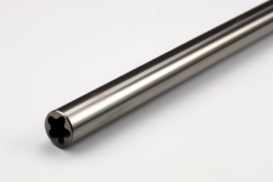
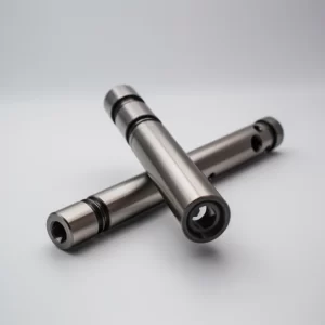
What steel should I use for my precision shaft application?
Use 1045 carbon steel for most precision shafts – it machines to tight tolerances and accepts heat treatment well. 4140 costs more without significant design advantages. Focus your design effort on geometry that enables precision rather than premium materials.
Shaft precision depends more on good design practices than steel grade selection. Length-to-diameter ratios and bearing surface design matter more than material choice for achieving tight tolerances.
Design for Achievable Tolerances: Start with ±0.002″ tolerances for prototypes – tighten only if assembly testing proves tighter specs necessary. Many precision requirements are imaginary – test function before over-specifying. We see 40% cost savings when engineers relax unnecessary tight tolerances.
Length-to-Diameter Guidelines: Keep L/D ratios under 8:1 for best tolerance control. Longer shafts deflect during machining, making tight tolerances difficult. If you need longer shafts, design larger diameters where possible, or break into shorter segments joined with couplings.
Bearing Surface Design: Design bearing surfaces at least 0.5″ long for stable machining and proper bearing contact. Avoid very short bearing surfaces under 0.25″ – they’re difficult to machine accurately and provide poor bearing support.
Feature Transition Design: Use generous radii between different diameters – minimum 0.030″ for precision work. Sharp shoulders create stress concentrations and machining difficulties. Gradual transitions machine more accurately than abrupt diameter changes.
Heat Treatment Design Considerations: If you need surface hardening, design symmetric geometry to prevent warping. Avoid one-sided features like keyways near shaft ends – they cause uneven distortion. Plan keyways and other features after heat treatment when possible.
Assembly Design Tips: Design realistic press fit tolerances – extremely tight fits may gall during assembly. Plan for thermal expansion in long shafts. Consider how the shaft will be handled during assembly – very long thin shafts bend easily.
Design Takeaway: Focus on good geometric design – proper L/D ratios, adequate bearing lengths, generous radii between features. Start with relaxed tolerances and proven materials like 1045. Optimize geometry before upgrading to expensive materials or ultra-tight tolerances.
Conclusion
Steel selection depends on your part’s function, environment, and loads – not theoretical properties. Start with 1018 for general parts, 1045 for shafts, and 304 stainless for corrosion resistance. Focus on good design geometry before upgrading to premium materials. Contact us to explore manufacturing solutions tailored to your steel part requirements.
Frequently Asked Questions
Thread after heat treatment when possible – heat treatment distorts threads and may prevent assembly. If you must thread before heat treatment, specify 25% larger thread engagement length to accommodate distortion. Consider pressed-in threaded inserts as an alternative.
Add 0.060-0.125″ on each surface for rough material removal. For heat-treated parts needing finish machining, allow 0.010-0.020″ extra. Castings or forgings may need 0.125-0.250″ depending on surface quality. Insufficient stock leads to incomplete cleanup and poor surface finish.
Ra 125 μin works for most general applications. Bearing surfaces need Ra 32 μin or smoother. Food contact requires Ra 32 μin for cleanability. Cosmetic surfaces may need Ra 16 μin. Smoother finishes add time and cost – only specify what function requires.
Design optimization usually beats material upgrades. Adding ribs, gussets, or forming operations can triple strength without changing materials. A simple 90° bend doubles effective stiffness. Try geometry improvements before specifying expensive steel grades – it’s often cheaper and more effective.
For most CNC steel parts, ±0.005″ is achievable with standard processes. Going tighter than ±0.002″ often requires secondary operations like grinding, significantly increasing cost. Reserve tight tolerances for functional features only – applying ±0.001″ to non-critical dimensions can double machining time.
Avoid deep narrow pockets (depth > 3x width), sharp internal corners under 0.030″ radius, and thin walls under 0.125″ thick. Long unsupported features and complex undercuts also create difficulties. If your CAD model looks difficult to reach with tools, it probably is.